Carbon Film Heater
Carbon Film
Installation Instructions
Contents
- Page 2 Product Overview
- Page 3 Pre-Installation & Electrical Provision
- Page 4 Insulation Underlay - Installation
- Page 5 Carbon Film Installation - Under Wood/Laminate Flooring
- Page 8 Notes & Trouble shooting
Carbon Film Heaters
Installation Instructions
Page 2
Product Overview
Thank you for selecting our electric underfloor heating system. Before you begin installing please read through these instructions carefully & check that you have all the components required.
The system requires a mains voltage 230V supply & must be connected in compliance with building regulation Part 'P' approved document and IEE 16th Edition.
Important Notes:
- Due to their moisture content, solid and kiln dried wood floor coverings should be laid, but not fixed, to allow acclimatisation with the heating system energized before final fixing. Allowances should be made for expansion. Refer to manufacturers instructions.
- Laminate and veneered/engineered flooring needs to have an allowance made for expansion. Refer to manufacturers instructions.
- The Carbon Heating Film, when installed under a wood floor, will heat the floor to a temperature of 27°C. This is the limit to which most wood floors can be heated to. Consult wood flooring manufactures technical details for further information. Please note that the surface temperature of the wood flooring under rugs and flush or low profile furniture may exceed 27°C if not monitored.
- If other floor finishes are to be installed over the carbon film, e.g. Carpet, Vinyl etc, a stable floating floor must be constructed. Heat-Pak® flooring is recommended for this application, which is available from your underfloor heating supplier, to give a smooth and thermally conductive sub-floor.
Contents of Heating Kit:
• Carbon heating film with cold connections made
• 6mm Foam Insulation Underlay
• Digital Programmable Thermostat
• Floor Probe
• Floor plan showing element layout
• 20Amp push fit cable connectors & connection box
• Polyethylene Sheet (Moisture Barrier)
• Factory test sheet with individual resistance readings
• Warranty / Guarantee Certificate

Carbon Film Heaters
Installation Instructions
Page 3
Pre - Installation
First unpack & identify all components (a list of supplied components is on page 2) and check the layout - see supplied floor plan (example Fig. 2)
Ensure that the sub-floor (concrete or timber) is clean, dry & free from dust & debris. The floor should also be suitably level to take the kind of flooring that you will be laying. Some types of wood plank flooring have a tolerance of just a mm or two per linear metre & we strongly recommend that your floor fitter surveys the floor before the heating is installed.

Fig. 2
Additional items to aid installation
Stanley / Craft Knife
Double Sided Adhesive Tape
Self Adhesive Cloth Tape (Duct Tape)
Multi - Meter
Electrical Provision

Fig. 3
Make the electrical provision as per the diagram Fig.3.
The circuit must incorporate a 30mA RCD protection
For installations below 13 Amp, A fused spur or combined spur / RCD is recommended.
For installations over 13 Amp a suitable isolated supply should be provided incorporating 30mA RCD protection.
The thermostat rating is 15 Amps & this is capable of controlling approx 3450 watts of heating film (most domestic installations are within this figure). If the system supplied is over 3.45 kW it will be subject to a more comprehensive electrical installation. (Your electrician will be able to advise you on this).
Note: all electrical connections should be made in compliance with building regulation Part 'P' and the IEE 16th Edition.
Carbon Film Heaters
Installation Instructions
Page 4
Insulation Underlay - Installation
Notes:
The foam underlay should be cut with a Stanley knife or similar.
STEP 1
Once you are satisfied that the sub-floor is suitable (see pre-installation notes page 3), lay out the insulation underlay to cover the entire floor area, except for the 50 mm gap. The foam underlay sheets should be laid with staggered joints Fig.4.
If laying a double layer (recommended in conservatories & other areas with a high heat loss) the second layer should be laid at right angles to the first.

Fig. 4
STEP 2
Leave a gap of approximately 50 mm at one edge of the room along where the cold cables are to be run, so as to allow them to sit flush under the floor covering when it is laid. For systems of more than 8 elements a gap wider than 50 mm may be required.
Using a length of 50 mm wide double sided tape on the sub floor within the gap that has been made in the underlay, can be used to hold the cold cables in place.

Fig. 5
STEP 3
If you wish, you can join the sheets of underlay together to prevent them from moving apart. This can be done by taping the edges of adjoining sheets together with a self adhesive cloth tape (Duct Tape) Fig. 5
Carbon Film Heaters
Installation Instructions
Page 5
Under Wood / Laminate Flooring
Only LIGHT FOOTWARE should be worn. Avoid foot traffic on the heating elements and cold tail joints.
STEP 4
Unpack the heating elements for the room and check that you have all the elements detailed on the enclosed drawing & room test data sheet.

Fig. 6
STEP 5
Check the resistance of each element using a suitable electrical testing device.
A basic multi-meter will be sufficient to test the elements at this stage.
You can purchase a suitable test device from your underfloor heating supplier or most DIY stores stock similar products.
DO NOT continue without first testing each element.
The desired resistance readings for each element are listed on the enclosed room test data sheet. A sample of the data sheet is shown in fig. 6. The reading should be within the Design Resistance Reading Range e.g a reading of 223Ω for the range circled in the example fig 6 is acceptable.
Note. The cold cables are double Insulated, a colored outer and a clear inner.
STEP 6
Unpack the heating elements for the room and check that you have all the elements detailed on the enclosed drawing & room test data sheet.

Fig. 7

Fig. 8
Carbon Film Heaters
Installation Instructions
Page 6
STEP 7
Below each of the "cold tail" joints form a cut out in the foam underlay to allow the plastic cover of the joint and the cold tail itself to lay within the underlay. Fig. 9
The cut out for the cold tail should extend to the 50 mm gap at the edge of the room.
If you have installed more than one layer of foam underlay, only form the cut-outs in the top layer.
STEP 8

Fig. 9
If used, peel the backing from the double sided tape that was fixed into the 50 mm gap at the edge of the room.
Starting from the point furthest from the connection box, run the cold tails from each element along the room perimeter, fixing them to the exposed double sided tape or if tape is not used, lay them carefully in the gap.
DO NOT run the cold tails under the heating elements.

Fig. 10
STEP 9
Once the cold tails are in position a resistance test needs to be performed on each individual element for a second time. The desired resistance readings for each element are listed on the enclosed room test data sheet.
Record the actual reading in the box provided on the data sheet. This is a requirement of the guarantee and MUST be performed at this stage. The data sheet needs to be retained on site with the heating system.
Note. The cold cables are double insulated, a colored outer and a clear inner.
STEP 10
The cold tails can now be joined in parallel at the junction box using the 8-way electrical connectors provided.
The junction box should be a double gang blank fronted box of a minimum 25 mm depth. Fig. 11
The paralleled cold tails should be routed to the junction box and connected to a suitably sized supply cable from the thermostat. See Fig. 2 Page 3
Note. The cold cables are double insulated, a colored outer and a clear inner.

Fig. 11
Carbon Film Heaters
Installation Instructions
Page 7
STEP 11

Position the floor sensor. If installing Heat-Pak® over the carbon system, refer to separate instructions regarding the floor sensor.
For standard installation, the tip of the sensor should be approximately 300 - 500 mm from the edge of the room with the tail of the probe running back to the thermostat via the 50 mm cold tail gap. Fig. 12. Form a channel in the foam underlay, in between two of the elements running into the cold tail gap. Press the sensor into the channel and tape in place with self adhesive cloth tape.
The sensor wire can be shortened or if required lengthened up to 50 m with a minimum 0.75 mm² 2-core flex cable. This connection should be located above floor level ideally within the cold tail junction box.
It is advisable to mark on the installed location of the sensor tip, on the floor plan for future reference.
Test the resistance of the floor probe. Refer to the label on the floor probe wrapper for desired resistance readings. Make a note of the reading.
STEP 12
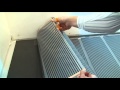
When you are satisfied with the layout, cover the heating elements with the plastic sheet/moisture barrier provided. The grade of PE-Sheet supplied will depend upon what is being installed over the system. If a wood floor, engineered wood or laminate floor is being laid, a 100micron sheet (clear) will be provided. When fitting Heat-Pak® over a carbon heating system a 200micron sheet (coloured blue) has to be used. The joints of the sheeting have to overlap by at least 20 cm. These overlaps have to be sealed over their total length with a self-adhesive PVC cloth tape (Duct Tape).
STEP 13
The floor finish can now be laid directly over the moisture barrier in accordance with the flooring manufacturers instructions. Under no circumstances should a separate underlay be installed at any point between the heating element and the floor finish. Ensure that the floor finish has been acclimatised prior to installation to avoid excessive shrinkage when heated. Refer to the notes on page 2 of this manual.
During the process of laying the floor, care should be taken not to damage any of the heating elements or cold tails. A spare sheet of foam underlay or a board, can be used to kneel on to help spread weight.
STEP 14
Once the floor finish has been laid, perform resistance tests on the floor probe and across the feed cable that connects the thermostat to the junction box, to ensure that no elements have been damaged during the flooring installation. The desired resistance reading for the heating system is at the bottom of the room test data sheet and should be within the tolerance of +10 –5%. Record the final readings on the guarantee certificate.
Once this test has been completed, final connections to the thermostat can be made. See Separate installation instructions for the thermostat.
Carbon Film Heaters
Installation Instructions
Page 8
Notes
- Electric underfloor heating is designed to run at low temperatures and can have a slightly slower warm-up time than conventional heating. This can be countered by using the features of the programmable thermostat instead of switching the system on or off.
- If installed in new buildings and especially conservatories, the heating period may be affected by the moisture content within the building. All new floor constructions and new buildings should be fully dried out before fitting wood, engineered wood or laminate flooring.
- The carbon film heating system is primarily designed to heat wood, engineered wood or laminate flooring. With such materials it is important to control the temperature to which they are heated. The industry standard for most wood flooring products is 27°C. Be aware that the carbon film heating system is capable of heating above this temperature and is only limited by the thermostat and the temperatures that it is set to operate to.
Electrical Notes
Each individual heating element is designed to accommodate a current carrying capacity of up to 10 Amps and should be connected in parallel at the junction box.
Consideration must be given by the electrical contractor in respect of the individual heating circuit ratings relative to the thermostat rating, circuit breakers, interconnecting cable sizing and switched contactors where the load of the heating system exceeds the rating of a single thermostat. Good wiring practice must be observed and the wiring must comply with the IEE 16th edition regulations.
The electrical installation must incorporate a 30 mA RCD Protection
Trouble shooting and FAQ’s
Q. When I perform the resistance test on the heating element I cannot get a reading.
A. Check that the test equipment you are using is set to read Ω and that both the inner and outer cable insulation sheaths have been removed.
Q. What size cable should be used to connect the thermostat to the junction box?
A. The size of the cable will vary depending upon the electrical load required for the heating system. Therefore this cable needs to be correctly sized by the electrician.
Q. The heating elements are slightly too long, can they be cut?
A. Yes. The element should be cut across it’s width, along a clear section, in line with the cutting marks on either edge of the element. Once cut, the ends of the copper conductors need to be sealed either re-using the green stickers from the end of the off-cut or use electrical insulation tape.
Q. Can the elements be overlapped?
A. Under no circumstances should the heated areas of the elements be overlapped. Only the clear spoils at the edge of the element can be over lapped
call us at 00389 47 203 900
Electric heating products of Electrolux of Macedonia and solutions are applied almost everywhere and anywhere you can imagine. Electric heating is used in a wide range of applications; inside and outside residential houses, apartments, public buildings, in the infrastructure, sports fields and even in more specific areas ranging from elevators, trains to airports and highways.Why electric heating? Electric heating of Electrolux of Macedonia a good answer to rising energy costs.As the world faces rising gas prices and supply uncertainty, electric heating powered by electricity from renewable energy sources is gaining importance as a valuable and sustainable heating option. Indeed, demand for electricity is forecast to grow to 30% in 2030 and to reach 50% by 2050 as we make the transition to climate neutrality. By 2050, the European Commission is aiming for 84 percent of this demand to come from renewable energy sources which will significantly decrease CO2 emissions.When combined with modern, intelligent controls electric heating can make grids smarter and facilitate renewable energy consumption. And moreover, with the use of electric heating, no harmful substances are emitted to the air or to the soil. Electric underfloor heating is a major opportunity for Europe. This can play a significant role in helping Europe reduce emissions, increase energy efficiency in buildings, and ultimately enable Europe to meet its ambitious climate targets. Electric heating is cost efficient solution.Electric underfloor heating of Electrolux of Macedonia in combination with solar PV is perceived for the most cost-efficient heating solution when it comes to highly insulated residential buildings. Electric underfloor heating of Electrolux of Macedonia is also set to become cheaper for consumers than traditional gas, liquid and solid fuel technology. Electric heating enables a comfortable room temperature with the lowest possible energy consumption. Room temperature can be reduced by 1 - 2 °C on average compared to traditional radiator heating, saving energy use and costs. 99% of the energy consumed by the electric underfloor heating is converted into heat, thus maximizing its energy efficiency and avoiding unnecessary energy losses by having to circulate water, for example. Why is electric heating energy efficient? An electric heating system achieves the required temperature quickly depending on the floor construction, so rooms can be heated only when required for amazing energy savings. Together, the positioning of the source of heat under the floor and very precise thermostatic control ensure an exceptionally high level of energy utilization efficiency, for reduced energy consumption without compromising thermal comfort. Indoor comfort with electric underfloor heating Electric heating for indoor ensures comfortable room temperatures, be it at home, at the office, in a workshop, sports hall or virtually anywhere where comfortable heat is required. Equally important is the fact that our floor heating system can be installed in all floor types whether they are new concrete or wooden floors or renovated floors. Roof protection system.The ice and snow melting system for roofs and roof gutters can be applied for virtually any type of roof constructions to prevent melt water accumulation in roof gutters and to reduce damage to constructions like frozen facades and roofs. The typical applications are roof constructions, roof gutters, down pipes, flat roofs and valley gutters. Pipe-tracing solutions. Liquid supply systems, such as fresh water pipes, waste water pipes, cooling water pipes, supply water pipes and sprinkler systems can be prevented from freezing during winter times, with electric heating frost protection systems. Ground ice and snow melting system .Large outdoor spaces, such as car parking areas, driveways, pavements, outdoor steps, loading platforms, ramps, bridges and drainage areas can be cost-efficiently protected during winter times, by ice and snow melting applications. Domestic hot water.The electric heating system for domestic hot water maintains water supply at the required temperature level, provides appropriate disinfection to suppress the Legionella bacteria, reduces water waste as you get hot water immediately and savings when a circulating pipe system is unnecessary. Cold stores. In areas where very cold dry air meets warm moist air, the moisture contained in the warm air flow may settle on the cold surface and turn into ice. Cold store solutions prevent frost heave and ensure frost protection in industrial buildings, supermarkets with cold rooms, cold stores and ice stadiums. Asphalt ice and snow melting system.Installation of the Ice & Snow Melting System ensures a steady solution to address cold weather-related problems. Main purpose of the system is to melt and remove snow and ice from ground surfaces.Sport fields.Electric heating in the sport fields or stadiums serves as a growth and restoration stimulator for natural grass. It ensures a better pitch that can extend the playable season, irrespective of the season or location and serves as an energy efficient solution preventing the field from being adversely affected by frost and snow during the winter. Vineyards.Electric heating protects grapes against frost damage and offers a sustainable solution for clean future through low energy consumption during the frost period, saving up to 87% of the harvest.
Веднаш по своето основање во 1984-та година, Фирмата Електролукс ja започнува својата работа со производство, продажба и монтажа на плочи за греење и калорифери, по што го добива своето име. Истовремено станува застапник на светски познатиот DEVI Denmark, првиот и најголем производител на електрични грејни кабли и мрежици кои се користат за подно греење во домови, комерцијални и индустриски објекти. DEVI Denmark во својата производна линија нуди решенија за надворешни услови за топење на снег и мраз, заштита од мрзнење на олуци, цевки, патеки и подести, скали, стојалишта, гаражни рампи, надворешни тераси, мостови, антени итн. Навистина е широка и разновидна примената на грејните кабли, која во пракса се потврди и во наши услови. DEVI Denmark денес е дел од групацијата Danfoss.
Во 1990 година почнува соработка и застапништво со повеке европски и светски компанија АЕG, Holland Heater,Thermor која е дел од групацијата Atlantic International со што формира мрежа од продажни места низ Македонија, каде се продаваат електрични конвектори, зрачечки панели, радијатори, регистри за бања и електрични бојлери. Сите производи се одликуваат со врвен квалитет, економичност, безбедност и сигурност при работа. И денес Тhermor ,AEG е познат како број еден во Македонија со безброј задоволни корисници.
Низ годините Electrolux ја збогатува својата продажна програма со електрични грејни кабли од чешкиот производител Fenix кој многу брзо се издигна на европскиот пазар и ги следи најновите трендови за загревање на домови и индустриски објекти. Најголем дел од изведените објетки низ Македонија се од Fenix – Чешка.
Вистински хит во светот е најновиот производ за подно греење – грејна филм фолија Hotfilm која Electrolux ја донесе во Македонија од најголемиот производител од Јужна Кореја. Hotfilm е идеално решение за домашно греење во многу верски објекти – особено многу џамии во Македонија се опремени на овој начин поради лесната и практична монтажа.
Во 2010 година Electrolux отвори нов сектор, првенствено за прочистување на водата за пиење во домашни услови – јонизатори за вода од реномираниот производител Nobel од , а подоцна системи за реверзно-осмотска филтрација на водата од европскиoт производители Polaqua i Amii и јонски изменувачи за отстранување на бигор од водата од унгарскиот производител Euro-clear Ltd. Electrolux е застапник и на италијанскиот Aqua Brevetti чии производи се единствени и патентирани за отстранување на бигор и заштита од корозија на електричните уреди во домаќинствата како бојлери, машини за перење алишта и садови итн. Со својата палета на производи Electrolux ги покрива сите проблеми кои се однесуваат на прочистување и подобрување на водата за пиење со цел превенција и заштита на здравјето на луѓето.
Phone: +389 (0) 47 203 900 mob.++389 70 237 108 viber/ WhatsApp ,Phone: +389 (0) 2 329 8 130 mob.++389 70 237 124 viber/ WhatsApp
Phone Factory Frinko Electrolux: +389 (0) 47 203 330 +389 (0) 2 322 5 230
Electrolux Macedonia.Street Brakja Mingovi 18 PO Box 52
7000 Bitola North Macedonia
Copyright © 2013 Electric Underfloor Heating.
All Rights Reserved.